Introduction
Traffic Engineering (TE) has become an indispensable function in many large and small Networks alike. One key objective of modern TE is the optimization of resource utilization. In particular, it is generally desirable to ensure that subsets of network resources do not become over utilized or congested while other subsets along alternate feasible paths remain underutilized. Therefore, a central function of TE is to efficiently manage bandwidth (BW) resources. Let us consider figure 1 below. Due to the resulting IGP shortest path (SPF) computation (SPF algorithms optimize based on a simple additive metric) all data flows between R1 and R6/R7 will converge on the {R1, R2, R5, R6/7} path across the network leaving the subset of the network, {R1, R3, R4, R5} left unused.
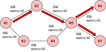
Figure 1: Fish Network
Thus our current IGPs, based on SPF algorithms, contribute significantly to congestion problems since they lack bandwidth availability and traffic characteristics as factors considered in routing decisions.
TE Process Model
Bandwidth optimization is fundamentally a control problem. In the TE process model, the Operator, or a suitable Automaton, acts as a “Controller” in an adaptive feedback control system. This system includes:
- A set of interconnected network elements (IP/MPLS network)
- A network state/topology monitoring element
- A network performance monitoring element
- A network configuration management element
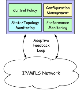
Figure 2: TE Process Model
The Operator/Automon formulates a control policy, observes the state of the network through the monitoring system, characterizes the traffic, and applies control actions to drive the network to an optimal state. This can be done reactively, based on the current state of the network, or proactively, based on a predicted future state.
Protocol Considerations
In the following sections we will explore how BW optimization can be achieved using either RSVP-TE or Segment Routing(SR). The sections will describe a high-level solution for each, the components required and briefly highlight a few behavioral and operational differences.
BW Optimization using RSVP-TE transport LSPs
RSVP-TE supports both a centralized, i.e. Controller augmented, or distributed, i.e. Router control-plane augmented, adaptive feedback loop for BW optimization, aka RSVP-TE Auto-Bandwidth. As such, an ingress router may monitor the ingress traffic load of an LSP and automatically adjust its LSP’s BWs based on the actual traffic flowing through that LSP. LSPs can therefore be setup with some minimum (or zero) BW value such that the automatic monitoring of the traffic flows results in BW adjustments each “adjust-interval” period as the flow of actual traffic rises and falls. The BW adjustments use the ‘make-before-break’ signaling method so that there is no interruption to traffic flow as the paths of LSPs change.
As you can see in figure 3, below, the congestion problem highlighted in figure 1 has been alleviated since the routing and signalling of the RSVP-TE LSPs now accounts for the maximum and available BW of each link along the paths and the required BW of each LSP on the network is known. One difference between the distributed vs. centralized feedback loop deployment options is the additional communication protocols required for the centralized option since the real-time network state (paths, data-plane statistics, network topology, etc.) must be synchronized with the Controller platform and new path and policy decisions must be programmed back into the the network. In the distributed deployment, each ingress router maintains a local and autonomous feedback loop along with local policy configuration.

Figure 3: Distributed & Centralized Feedback loop options
It’s worth highlighting, that hybrid deployments where centralized control of some LSPs and distributed control of other LSPs is possible via per LSP control delegation. One key aspect of using RSVP-TE for BW optimization is that both deployment options leverage per LSP independent BW control, as depicted in figure 4 below. As you can see, each LSP’s BW profile is maintained independently to ensure per LSP optimal routing and overall network BW optimization.
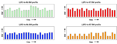
Figure 4: Dynamic & Adaptive LSP BW optimization
While the above solution(s) provides a very efficient network BW optimization sometimes there is a need for additional granularity. Consider a scenario where the ingress load for a given LSP exceeds the BW of an individual link along a path through the network. In this example, RSVP-TE provides a solution known RSVP-TE container tunnels. RSVP-TE multipath leverages an additional dynamic bandwidth management policy thus enabling the ingress router to dynamically add and remove member(sub) LSPs through a process called LSP splitting and LSP merging, respectively. A RSVP-TE multipath tunnel enables load balancing across multiple point-to-point sub LSPs between the same ingress and egress routers. Sub LSPs can also be re-optimized with different bandwidth values in a make-before-break manner. Figure 5, below, illustrates a RSVP-TE LSP used in the previous example enabled for multipath. As you can see the same LSP is now comprised of 2 sub-LSPs that are routed individually across the network for fine grained BW management.
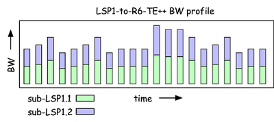
Figure 5: RSVP multipath(TE++) LSP
In conclusion, the key properties of RSVP-TE LSPs that enable fine grained BW optimization is unique per LSP labels that serve as data-plane statistic counters on each node that an LSP traverses along with integrated Connection Admission Control(CAC). Let us now look at how BW optimization can be approached using Segment Routed LSPs.
BW Optimization using SR-TE transport LSPs
Figure 6, below, depicts a SR enabled variant of figure 3 with Node-SIDs and Anycast-SIDs assigned. The SR-Paths with corresponding label stacks are also shown in the diagram. The SR-Paths are created so as to maximize the network BW resource utilization. Like the RSVP-TE case, they may need to be re-routed occasionally to balance utilization and ensure BW optimization. Also note, the SR-Paths are inherently ECMP aware.

Figure 6: Centralized control of a SR Domain
SR paths do not have separate control or forwarding state in any node other than the head-end. Traffic measurement at the head-end node is insufficient to determine the contribution of each SR path to the congestion on the link because of the presence of ECMP or Weighted ECMP load-balancing. Furthermore, per-SID traffic measurement on every interface gives some information about the traffic carried, as depicted in figure 7 below, but is not sufficient to correctly measure traffic carried by each SR path on the link for granular BW per SR-TE LSP optimizations. If it were possible to identify to which SR path each packet belonged, that information could be used by the external Controller to re-route SR paths for maximizing BW optimization.
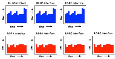
Figure 7: Per interface SID statistics
Figure 7 depicts the 2 paths available from R1 to R6/7. The blue graphs represents the path {r1, r2, r5, r6} and the red graphs represent the path {r1, r3, r4, r5, r7}. Notice that the BW contribution of the 4 paths depicted in figure 6 are not distinguishable in order to make per LSP BW optimizations and optimize the networks resources. As such, if congestion occurs, there is no way to determine which SR-TE LSPs to reroute in order to alleviate the congestion.
In conclusion, there is currently no reliable, robust means of using Segment Routing to provide a BW optimization due impart to the nature of SR’s shared label, minimal network state, architecture. A number of solutions are being proposed within the industry, the foremost being the SPRING Traffic Accounting proposal, draft-hegde-spring-traffic-accounting-for-sr-paths-00
Conclusion
Traffic Engineering is an indispensable function in most backbone wide area networks. A key objective of modern TE is the optimization of resource utilization. RSVP-TE has a long history and a large box of tools to leverage while SR needs to leverage newer tools or add state back to the network to achieve better resource utilization.
Additional Reading
RSVP Auto-bandwidth: https://www.juniper.net/documentation/en_US/junos/topics/concept/mpls-automatic-bandwidth-allocation.html
RSVP Multipath:
https://www.juniper.net/documentation/en_US/junos/topics/concept/dynamic-bandwidth-management-overview.html
Segment Routing TE: https://www.juniper.net/documentation/en_US/junos/topics/concept/source-packet-routing.html
SPRING Traffic Accounting: https://tools.ietf.org/html/draft-hegde-spring-traffic-accounting-for-sr-paths-00
Northstar TE Controller: https://www.juniper.net/us/en/products-services/sdn/northstar-network-controller/