Background, Introduction and New Deployment Design
Juniper’s QFX5200 Ethernet Switch supports flexible 10GbE, 25GbE, 40GbE, 50GbE, and 100GbE interfaces for Ethernet connectivity, which delivers a line-rate, low-latency, and high-density platform for building large Hub-and-Spoke IP-fabric data center networks.
Previously, customers could apply Priority-based flow control (PFC) and enhanced transmission selection (ETS) to build lossless traffic flows. PFC facilitates the selection of data flows within links and tries to pause them, so that the output forwarding classes attached to the traffic flows do not overflow and drop packets. ETS supports link bandwidth allocation and provides each queue as well as each priority group with their maximum available transmitting bandwidth. If a forwarding class (queue) does not use its designed resource, ETS will allocate the unused bandwidth among the other forwarding classes in the priority group. This is in proportion to the minimum guaranteed rate (transmit rate) scheduled for each queue.
Currently, the QFX5200 does not support ETS, so a new mechanism for traffic scheduling and congestion management needed to be provided. During the PFC and Scheduling practice on QFX5200 switches on version of 17.4R1.16, a new combination designed for congestion control and traffic rate guarantee, has been proven. The main functions of this mechanism include:
- DSCP PFC packets generation based on traffic scheduling without Traffic Control Profile configuration on QFX5200
- A practical example for a new feature which is just introduced in 17.4R1 for QFX, pfc-priority, working on DSCP based PFC
- A real case traffic verification and negative cases are provided on the end of the article, which aims at proving this new mechanism working correctly from two aspects.
The following sections demonstrate this solution from the traffic profile, topology, configuration and result verification.
System Topology

Figure 1. System Topology
Flow Description and Traffic Profile
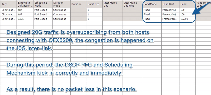
In this Scenario, both source hosts send a total of 20G bps unicast traffic to the QFX5200. Each of them is responsible for up to 10G bps, and the destination host sends 10,000 PPS (around 96M bps) unicast traffic back. When congestion happens on the 10G inter-link between the QFX5200 and QFX5110, the designed Class of Service kicks in, starts congestion control, and traffic allocation.
Layer 2 Information
- MAC Address 1: 00:10:94:00:00:01
- MAC Address 2: 00:10:94:00:00:02
- MAC Address 3: 00:10:94:00:00:03
Layer 3 Information
- IP Address 1: 31.0.1.2/16, DSCP: 011000
- IP Address 2: 31.1.1.2/16, DSCP: 101000
- IP Address 3: 24.1.1.2/16, DSCP: 000000
Traffic Direction
- IP Address 1 ↔ IP Address 3
- IP Address 2 ↔ IP Address 3
Traffic Volume and MTU
- MTU: 1200 Bytes
- IP Address 1->10G bps -> IP Address 3
- IP Address 2->10G bps -> IP Address 3
- IP Address 3->5000 pps->IP Address 1
- IP Address 3->5000 pps->IP Address 2
System Configuration and Explanation
1 Class of Service Configuration on QFX5200
The configuration below focuses on a new combination of PFC and scheduling working on the QFX5200. In addition, the latest introduced feature, ‘pfc-priority’ is also explained. From the following example, we provided a scenario which contains traffic congestions on lossless queues. By scheduling the traffic, a proportion, 4:6, of traffic allocation should be seen during the congestion. And the pfc packets on some specific queue defined by pfc-priority will be observed.
-
Configuring Forwarding Classes
set groups pfc class-of-service forwarding-classes class q3 queue-num 3
set groups pfc class-of-service forwarding-classes class q3 no-loss
set groups pfc class-of-service forwarding-classes class q3 pfc-priority 3
set groups pfc class-of-service forwarding-classes class q5 queue-num 5
set groups pfc class-of-service forwarding-classes class q5 no-loss
set groups pfc class-of-service forwarding-classes class q5 pfc-priority 5
-
Configuring DSCP Classifier
set groups pfc class-of-service classifiers dscp dscp_classifier forwarding-class q3 loss-priority low code-points 011000
set groups pfc class-of-service classifiers dscp dscp_classifier forwarding-class q5 loss-priority low code-points 101000
-
Configuring Scheduler
set groups pfc class-of-service schedulers q3_4g transmit-rate percent 40
set groups pfc class-of-service schedulers q5_6g transmit-rate percent 60
-
Configuring Scheduler Map
set groups pfc class-of-service scheduler-maps q3_4g_q5_6g forwarding-class q3 scheduler q3_4g
set groups pfc class-of-service scheduler-maps q3_4g_q5_6g forwarding-class q5 scheduler q5_6g
-
Configuring DSCP Based PFC
set groups pfc class-of-service congestion-notification-profile dscp_011000 input dscp code-point 011000 pfc
set groups pfc class-of-service congestion-notification-profile dscp_101000 input dscp code-point 101000 pfc
-
Configuring Class of Service Interface
set groups pfc class-of-service interfaces xe-0/0/31:0 congestion-notification-profile dscp_011000
set groups pfc class-of-service interfaces xe-0/0/31:0 classifiers dscp dscp_classifier
set groups pfc class-of-service interfaces xe-0/0/31:1 congestion-notification-profile dscp_101000
set groups pfc class-of-service interfaces xe-0/0/31:1 classifiers dscp dscp_classifier
set groups pfc class-of-service interfaces xe-0/0/6:0 scheduler-map q3_4g_q5_6g
2 Interface and Routing Protocols on QFX5200
In this scenario, three layer-3 interfaces with IPv4 and OSPF routing protocol are employed for connectivity.
-
Configuring Interfaces
set groups pfc interfaces xe-0/0/6:0 unit 0 family inet address 6.11.1.0/31
set groups pfc interfaces xe-0/0/31:0 unit 0 family inet address 31.0.1.1/16
set groups pfc interfaces xe-0/0/31:1 unit 0 family inet address 31.1.1.1/16
-
Configuring OSPF
set groups pfc protocols ospf area 0.0.0.0 interface xe-0/0/6:0.0
set groups pfc protocols ospf area 0.0.0.0 interface xe-0/0/31:0.0
set groups pfc protocols ospf area 0.0.0.0 interface xe-0/0/31:1.0
3 Interface and Routing Protocol on QFX5110
Here the QFX5110 has no Class-of-Service configuration and works as an auxiliary role to transmit the traffic.
-
Configuring Interfaces
set groups pfc interfaces xe-0/0/24 unit 0 family inet address 24.1.1.1/16
set groups pfc interfaces xe-0/0/16 unit 0 family inet address 6.11.1.1/31
-
Configuring OSPF
set groups pfc protocols ospf area 0.0.0.0 interface xe-0/0/24.0
set groups pfc protocols ospf area 0.0.0.0 interface xe-0/0/16.0
A Customer Oversubscription Case and Lossless Transmission Scenario
1 Lossless Data Transmission
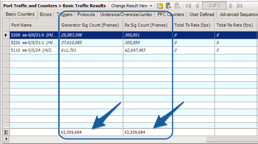
Suppose end user hosts oversubscribed their traffic to 20G, sending packets through the two switches as shown in Figure 2. Since the DSCP PFC is properly functioning during the traffic oversubscribing, there is no packet loss in this scenario as shown in Figure 3

Figure 2. Traffic Load Table

Figure 3. Packets I/O Statistics
2 Distribution of Traffic by scheduler
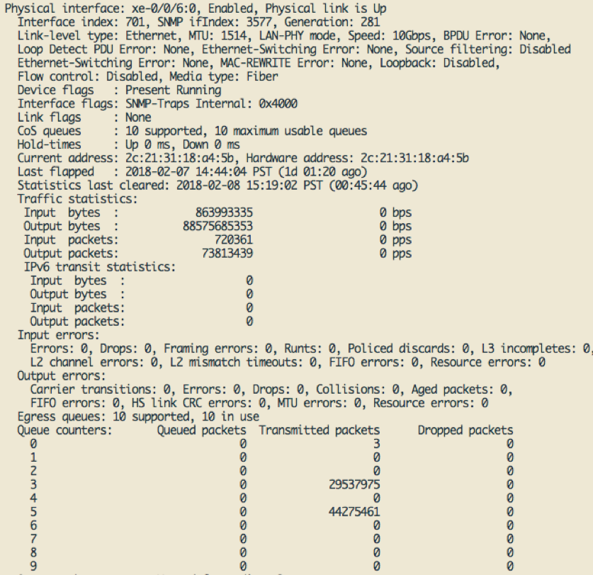
As mentioned above, ETS is not supported in the QFX5200. This mechanism, combining DSCP PFC and scheduler is introduced and as a result, Figure 4 shows that the packet delivery is guaranteed during oversubscription, as previous designed ratio (29537975:44275461 ≈ 40:60), for end users. As a result, the data of other customers is properly protected from the traffic congestion.

Figure 4. Traffic Allocation
3 DSCP PFC Generation as Designed in New Feature ‘pfc-priority’
The following example shows the result on how pfc-priority works on the back pressure pfc packets. From Figure 5, the pfc priority of 3 is mapped to queue 3 (q3). This means when the pfc packets are generated by corresponding DSCP code, the pfc will be transmitted to queue 3 (q3). And then, to verify the result, Figure 6 provides the pfc packets number in the right queue defined by pfc-priority.
Figure 5. ‘pfc-priority’ keyword queue mapping
 Figure 6. DSCP PFC Generation in Target Queue
Absence of this DSCP PFC Combining with Scheduler
Without the binding scheduler on the outgoing interfaces; although the congestion traffic is going through traffic proportion 4:6, it is not guaranteed, which means either customer may not by satisfied by their requirement.
deactivate groups pfc class-of-service interfaces xe-0/0/6:0 scheduler-map

Figure 7. Traffic Allocation when oversubscription
Moreover, if we did not define the pfc-priority, then the pfc packets would egress to another customer queue, rather than the user in queue 3 mentioned in Figure 5. As a result, this behavior will impact another customers’ data. The following example shows the pfc packets generated by queue 3 (q3) are egressing to queue 1 (q1), after deleting the pfc-priority definition on QFX5200.
-
Delete pfc-priority configuration
delete groups pfc class-of-service forwarding-classes class q5 pfc-priority
delete groups pfc class-of-service forwarding-classes class q3 pfc-priority

Figure 8. without keyword ‘pfc-priority’
Conclusion
From Junos OS Release 17.4R1 forward, customers may use DSCP values in Layer 3 IP headers of incoming traffic to enable PFC on Layer 2 access interface and Layer 3 interface. With the newly released QFX5200, proper traffic congestion management based on DSCP with scheduling is verified. This practice provides several real cases for this requirement from both sides. Consequentially, during traffic oversubscription, we have clearly demonstrated the lossless data transmission as well as the guaranteed ratio of traffic, as defined, for future customers.